ParaMgmt: Interacting with thousands of servers over SSH (part 1)

Google-datacenter_2

While working at Google in the Platforms Networking research group, I was tasked with running network performance benchmarks on large clusters of servers. Google has their own internal application scheduling system, but for unmentionable reasons, I couldn’t use this for my tests. I needed 100% control of the servers. I resulted to SSH and SCP.

A common benchmark assigns some servers as senders and others as receivers. A typical test sequence would go something like this:

  1. Build the benchmark binaries on my local workstation.
  2. Copy the sender binary and receiver binary to the sender and receiver servers, respectively.
  3. Copy the configuration files to the servers.
  4. Run the test.
  5. Copy the results files from the servers back to my workstation.
  6. Parse and analyze the results.

This process became VERY tedious. As a result, I wrote a software package to do this more efficiently and productively. It is called ParaMgmt, and it is now open-source on GitHub (https://github.com/google/paramgmt). ParaMgmt is a python package designed to ease the burden of interacting with many remote machines via SSH. The primary focus is on parallelism, good error handling, automatic connection retries, and nice viewable output. The abilities of ParaMgmt include running local commands, running remote commands, transferring files to and from remote machines, and executing local scripts on remote machines. This package includes command-line executables that wrap the functionality provided by the Python package.

The GitHub page describes how to install the software. The easiest method is to use pip and the GitHub link:

nic@myworkstation$ pip3 install --user \
> git+https://github.com/google/paramgmt.git

All you need to use the software is a list of remote hosts you want to interact with. I’ll be focusing on the command-line executables in this post, so let’s start by making a file containing our hosts:

nic@myworkstation$ cat << EOF >> hosts.txt
> 10.0.0.100
> 10.0.0.101
> 10.0.0.102
> EOF

Now that we have our hosts file, let’s run some remote commands. There are 6 command line executables:

  • rhosts = Remote hosts – just prints each remote host.
  • lcmd = Local command – runs commands locally for each remote host.
  • rcmd = Remote command – runs commands remotely on each remote host.
  • rpush = Remote push – pushes files to each remote host.
  • rpull = Remote pull – pulls files from each remote host.
  • rscript = Remote script – runs local scripts on each remote host.

First make sure you’ve setup key-based authentication with all servers (tutorial). Now let’s use the ‘rhosts’ executable to verify our hosts file, and also try adding more hosts on the command line.

nic@myworkstation$ rhosts -f hosts.txt
10.0.0.100
10.0.0.101
10.0.0.102
nic@myworkstation$ rhosts -f hosts.txt -m abc.com 123.com
abc.com
123.com
10.0.0.100
10.0.0.101
10.0.0.102

Let’s verify that SSH works using the ‘rcmd’ executable:

nic@myworkstation$ rcmd -f hosts.txt -- whoami
rcmd [10.0.0.100]: whoami
stdout:
nic
rcmd [10.0.0.101]: whoami
stdout:
nic
rcmd [10.0.0.102]: whoami
stdout:
nic
3 succeeded, 0 failed, 3 total

You can see that we remotely logged in and successfully executed the ‘whoami’ command on each host. All 3 connections executed in parallel. ParaMgmt uses coloring as a better way to view the output. In our example, the execution was successful, so the output is green. If the command output text to stderr, ParaMgmt will color the output yellow if the command still exited successfully, and red if it exited with error status. Upon an error, ParaMgmt also states how many attempts were made, the return code, and reports the hosts that failed.

nic@myworkstation$ rcmd -f hosts.txt -- 'echo some text 1>&2'
rcmd [10.0.0.100]: echo some text 1>&2
stderr:
some text
rcmd [10.0.0.101]: echo some text 1>&2
stderr:
some text
rcmd [10.0.0.102]: echo some text 1>&2
stderr:
some text
3 succeeded, 0 failed, 3 total
nic@myworkstation$ rcmd -f hosts.txt -- \
> 'echo some text 1>&2; false'
rcmd [10.0.0.100]: echo some text 1>&2; false
stderr:
some text
return code: 1
attempts: 1
rcmd [10.0.0.101]: echo some text 1>&2; false
stderr:
some text
return code: 1
attempts: 1
rcmd [10.0.0.102]: echo some text 1>&2; false
stderr:
some text
return code: 1
attempts: 1
0 succeeded, 3 failed, 3 total

Failed hosts:
10.0.0.100
10.0.0.101
10.0.0.102

ParaMgmt has a great feature that makes it extremely useful, namely automatic retries. Commands in ParaMgmt will automatically retry when an SSH connection fails. This hardly ever occurs when you are communicating with only 3 servers, but when you use ParaMgmt to connect to thousands of servers potentially scattered across the planet, all hell breaks loose. The automatic retry feature of ParaMgmt hides all the annoying network issues. It defaults to a maximum of 3 attempts, but this is configurable on the command line with the “-a” option.

Now that we can run remote commands, let’s try copying files to and from the remote machines:

nic@myworkstation$ rpush -f hosts.txt -d /tmp -- f1.txt
rpush [10.0.0.100]: f1.txt => 10.0.0.100:/tmp
rpush [10.0.0.101]: f1.txt => 10.0.0.101:/tmp
rpush [10.0.0.102]: f1.txt => 10.0.0.102:/tmp
3 succeeded, 0 failed, 3 total

nic@myworkstation$ rpull -f hosts.txt -d /tmp -- \
> /tmp/f2.txt /tmp/f3.txt
rpull [10.0.0.100]: 10.0.0.100:{/tmp/f2.txt,/tmp/f3.txt} => /tmp
rpull [10.0.0.101]: 10.0.0.101:{/tmp/f2.txt,/tmp/f3.txt} => /tmp
rpull [10.0.0.102]: 10.0.0.102:{/tmp/f2.txt,/tmp/f3.txt} => /tmp
3 succeeded, 0 failed, 3 total

As shown in this examples, ParaMgmt is able to push and pull many files simultaneously. ParaMgmt is also able to run a local script on a remote machine. You could do this by doing an rpush then an rcmd, but it is faster and cleaner to use ‘rscript’, as follows:

nic@myworkstation$ cat << EOF >> s1.sh
> #!/bin/bash
> echo -n "hello "
> echo -n `whoami`
> echo ", how are you?"
> EOF
nic@myworkstation$ rscript -f hosts.txt -- s1.sh
rscript [10.0.0.100]: running s1.sh
stdout:
Welcome to Ubuntu 14.10 (GNU/Linux 3.16.0-39-generic x86_64)
hello nic, how are you?
rscript [10.0.0.101]: running s1.sh
stdout:
Welcome to Ubuntu 14.10 (GNU/Linux 3.16.0-39-generic x86_64)
hello nic, how are you?
rscript [10.0.0.102]: running s1.sh
stdout:
Welcome to Ubuntu 14.10 (GNU/Linux 3.16.0-39-generic x86_64)
hello nic, how are you?
3 succeeded, 0 failed, 3 total

There is one more really cool feature of ParaMgmt I should cover. Often times, the remote hostname should be used in a command. For instance, after a benchmark has been run on all servers and you want to collect the data from the servers using the ‘rpull’ command, it would be nice if there was a corresponding local directory for each remote host. For this, we can use the ‘lcmd’ executable, with ParaMgmt’s hostname replacement feature. Any instance of “?HOST” in the command will be translated to the corresponding hostname. This works with all executables and is even applied on text within scripts used in the ‘rscript’ executable.

nic@myworkstation$ lcmd -f hosts.txt -- mkdir /tmp/res?HOST
lcmd [10.0.0.100]: mkdir /tmp/res10.0.0.100
lcmd [10.0.0.101]: mkdir /tmp/res10.0.0.101
lcmd [10.0.0.102]: mkdir /tmp/res10.0.0.102
3 succeeded, 0 failed, 3 total
nic@myworkstation$ rpull -f hosts.txt -d /tmp/res?HOST -- res.txt
rpull [10.0.0.100]: 10.0.0.100:res.txt => /tmp/res10.0.0.100
rpull [10.0.0.101]: 10.0.0.101:res.txt => /tmp/res10.0.0.101
rpull [10.0.0.102]: 10.0.0.102:res.txt => /tmp/res10.0.0.102
3 succeeded, 0 failed, 3 total

Here is an example of using the hostname auto-replacement in a script. I’ve just added the “?HOST” to the previous script example:

nic@myworkstation$ cat << EOF >> s1.sh
> #!/bin/bash
> echo -n "hello "
> echo -n `whoami`
> echo "@?HOST, how are you?"
> EOF
nic@myworkstation$ rscript -f hosts.txt -- s1.sh
rscript [10.0.0.100]: running s1.sh
stdout:
Welcome to Ubuntu 14.10 (GNU/Linux 3.16.0-39-generic x86_64)
hello nic@10.0.0.100, how are you?
rscript [10.0.0.101]: running s1.sh
stdout:
Welcome to Ubuntu 14.10 (GNU/Linux 3.16.0-39-generic x86_64)
hello nic@10.0.0.101, how are you?
rscript [10.0.0.102]: running s1.sh
stdout:
Welcome to Ubuntu 14.10 (GNU/Linux 3.16.0-39-generic x86_64)
hello nic@10.0.0.102, how are you?
3 succeeded, 0 failed, 3 total

ParaMgmt is fast and efficient. It handles all SSH connections in parallel freeing you from wasting your time on less-capable scripts. ParaMgmt’s command line executables are great resources to be used in all sorts of scripting environments. To really get the full usefulness of ParaMgmt, import the Python package into your Python program and unleash concurrent SSH connections to remote machines.

Unix Domain Sockets vs Loopback TCP Sockets

Two communicating processes on a single machine have a few options. They can use regular TCP sockets, UDP sockets, unix domain sockets, or shared memory. A recent project I was working on used Node.js with two communicating processes on the same machine. I wanted to know how to reduce the CPU utilization of the machine, so I ran a few experiments to compare the efficiency between unix domain sockets and TCP sockets using the loopback interface. This post covers my experiments and test results.

First off, is a disclaimer. This test is not exhaustive. Both client and server are written in Node.js and can only be as efficient as the Node.js runtime.

All code in this post is available at: github.com/nicmcd/uds_vs_tcp

Server Application

I created a simple Node.js server application that could be connected to via TCP socket or Unix domain socket. It simply echos all received messages. Here is the code:

var assert = require('assert');
assert(process.argv.length == 4, 'node server.js <tcp port> <domain socket path>');

var net = require('net');

var tcpPort = parseInt(process.argv[2]);
assert(!isNaN(tcpPort), 'bad TCP port');
console.log('TCP port: ' + tcpPort);

var udsPath = process.argv[3];
console.log('UDS path: ' + udsPath);

function createServer(name, portPath) {
    var server = net.createServer(function(socket) {
        console.log(name + ' server connected');
        socket.on('end', function() {
            console.log(name + ' server disconnected');
        });
        socket.write('start sending now!');
        socket.pipe(socket);
    });
    server.listen(portPath, function() {
        console.log(name + ' server listening on ' + portPath);
    });
}

var tcpServer = createServer('TCP', tcpPort);
var udsServer = createServer('UDS', udsPath);

Client Application

The client application complements the server application. It connects to the server via TCP or Unix domain sockets. It sends a bunch of randomly generated packets and measures the time it takes to finish. When complete, it prints the time and exits. Here is the code:

var assert = require('assert');
assert(process.argv.length == 5, 'node client.js <port or path> <packet size> <packet count>');

var net = require('net');
var crypto = require('crypto');

if (isNaN(parseInt(process.argv[2])) == false)
    var options = {port: parseInt(process.argv[2])};
else
    var options = {path: process.argv[2]};
console.log('options: ' + JSON.stringify(options));

var packetSize = parseInt(process.argv[3]);
assert(!isNaN(packetSize), 'bad packet size');
console.log('packet size: ' + packetSize);

var packetCount = parseInt(process.argv[4]);
assert(!isNaN(packetCount), 'bad packet count');
console.log('packet count: ' + packetCount);

var client = net.connect(options, function() {
    console.log('client connected');
});

var printedFirst = false;
var packet = crypto.randomBytes(packetSize).toString('base64').substring(0,packetSize);
var currPacketCount = 0;
var startTime;
var endTime;
var delta;
client.on('data', function(data) {
    if (printedFirst == false) {
        console.log('client received: ' + data);
        printedFirst = true;
    }
    else {
        currPacketCount += 1;
        if (data.length != packetSize)
            console.log('weird packet size: ' + data.length);
        //console.log('client received a packet: ' + currPacketCount);
    }

    if (currPacketCount < packetCount) {
        if (currPacketCount == 0) {
            startTime = process.hrtime();
        }
        client.write(packet);
    } else {
        client.end();
        endTime = process.hrtime(startTime);
        delta = (endTime[0] * 1e9 + endTime[1]) / 1e6;
        console.log('millis: ' + delta);
    }
});

Running a Single Test

First start the server application with:

node server.js 5555 /tmp/uds

This starts the server using TCP port 5555 and Unix domain socket /tmp/uds.

Now we can run the client application to get some statistics. Let’s first try the TCP socket. Run the client with:


node client.js 5555 1000 100000

This runs the client application using TCP port 5555 and sends 100,000 packets all sized 1000 bytes. This tooks 8006 milliseconds on my machine. We can now try running with the Unix domain socket with:


node client.js /tmp/uds 1000 100000

This runs the client the same as before except it uses the /tmp/uds Unix domain socket instead of the TCP socket. On my machine this took 3570 milliseconds to run. These two runs show that for 1k byte packets, Unix domain sockets are about 2-3x more efficient than TCP sockets.
At this point you might be completely convinced that Unix domain sockets are better and you’ll use them whenever you can. That’s too easy. Let’s run the client application a whole bunch of times and graph the results.
I recently posted about a python package I created for running many tasks and aggregating the data. I thought this socket comparison would make a good example.

Running the Full Test

As mentioned, running the full test uses the Taskrun Python package (available at github.com/nicmcd/taskrun). The script I quickly hacked together to run the client application and parse the results is as follows:


import taskrun
import os

POWER = 15
RUNS = 10
PACKETS_PER_RUN = 100000

manager = taskrun.Task.Manager(
    numProcs = 1,
    showCommands = True,
    runTasks = True,
    showProgress = True)

DIR = "sims"
mkdir = manager.task_new('dir', 'rm -rI ' + DIR + '; mkdir ' + DIR)

def makeName(stype, size, run):
    return stype + '_size' + str(size) + '_run' + str(run)

def makeCommand(port_or_path, size, name):
    return 'node client.js ' + port_or_path + ' ' + str(size) + ' ' + str(PACKETS_PER_RUN) + \
        ' | grep millis | awk \'{printf "%s, ", $2}\' > ' + os.path.join(DIR, name)

barrier1 = manager.task_new('barrier1', 'sleep 0')
for exp in range(0, POWER):
    size = pow(2, exp)
    for run in range(0, RUNS):
        # Unix domain socket test
        name = makeName('uds', size, run)
        task = manager.task_new(name, makeCommand('/tmp/uds', size, name))
        task.dependency_is(mkdir)
        barrier1.dependency_is(task)

        # TCP socket test
        name = makeName('tcp', size, run)
        task = manager.task_new(name, makeCommand('5555', size, name))
        task.dependency_is(mkdir)
        barrier1.dependency_is(task)

# create CSV header
filename = os.path.join(DIR, 'uds_vs_tcp.csv')
header = 'NAME, '
for run in range(0, RUNS):
    header += 'RUN ' + str(run) + ', '
hdr_task = manager.task_new('CSV header', 'echo \'' + header + '\' > ' + filename)
hdr_task.dependency_is(barrier1)

# UDS to CSV
cmd = ''
for exp in range(0,POWER):
    size = pow(2, exp)
    cmd += 'echo -n \'UDS Size ' + str(size) + ', \' >> ' + filename + '; '
    for run in range(0, RUNS):
        name = makeName('uds', size, run)
        cmd += 'cat ' + os.path.join(DIR, name) + ' >> ' + filename + '; '
    cmd += 'echo \'\' >> ' + filename + '; '
uds_task = manager.task_new('UDS to CSV', cmd)
uds_task.dependency_is(hdr_task)

# TCP to CSV
cmd = ''
for exp in range(0,POWER):
    size = pow(2, exp)
    cmd += 'echo -n \'TCP Size ' + str(size) + ', \' >> ' + filename + '; '
    for run in range(0, RUNS):
        name = makeName('tcp', size, run)
        cmd += 'cat ' + os.path.join(DIR, name) + ' >> ' + filename + '; '
    cmd += 'echo \'\' >> ' + filename + '; '
tcp_task = manager.task_new('TCP to CSV', cmd)
tcp_task.dependency_is(uds_task)

manager.run_request_is()

Admittedly, this isn’t the prettiest code to look at, but it gets the job done. For both Unix domain socket and TCP socket, it runs the client application for all packet sizes that are a power of 2 from 1 to 16384. Each setup is run 10 times. Each test result is written to its own file. After all the tests have been run, the taskrun script creates a CSV file using all the test results. The CSV file can then be imported into a spreadsheet application for analysis.

Results

I ran this on an Intel E5-2620 v2 processor with 16GB of RAM. I imported the CSV into Excel, averaged the 10 results of each setup, then graphed the results. This first graph shows the execution time compared to packet size on a logarithmic graph.

Execution Time vs. Packet Size

The results shown here are fairly predicable. The Unix domain sockets are always more efficient and the efficiency benefit is in the 2-3x range. After noticing some weird ups and down in the graph, I decided to generate a graph with the execution times normalized to the TCP execution time.

Relative Execution Time vs Packet Size

I’m not exactly sure why the efficiency of Unix domain sockets varies as it does compared to TCP sockets, but it is always better. This is simply because Unix domain sockets don’t traverse the operating system’s network stack. The kernel simply copies the data from the client’s application into the file buffer in the server’s application.

taskrun – An easy-to-use python package for running tasks with dependencies and process management

Lately I’ve been running lots of network simulations. I’m always running the simulator over and over while varying the simulation parameters. I’ve also written some programs that parse the simulator output file and generate some CSV files and graphs. Each block of simulations is created in a new directory. Running the simulations by hand, and even by shell scripts, has gotten to be VERY tedious.

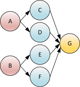
All my simulations have the same basic style: create a directory to hold a block of simulations, create sub-directories for each simulation, after the simulation completes run the first parsing program, after all simulations in a block have run and the corresponding first parsing program, run a second parsing program to generate graphs from the aggregate data from all simulations in the block. This process is often also parallelized many times across a second-level simulation parameter. As you can see, there is a great deal of parallelism, however, there are also a lot of dependencies. The dependencies create a simple directed acyclic graph (DAG).

In attempt at making the process of running simulations easier and faster, I created a Python package called taskrun. Taskrun has the following features:

  • Task dependency chaining: Each created task can list other tasks as its dependencies and can itself be a dependency for other tasks.
  • Parallelism throttling: A task manager is used to wait until a processor is available before starting a new task. Although the number of ready tasks might be large, it is more efficient to only run as many tasks at one time as there is processors on the machine. This reduces unnecessary cache thrashing and context switching. This can also be used to nicely share a community machine.
  • Simple task declaration: Tasks are easily declared and dependencies are easily chained. The syntax is easy to use and integrates very easily into for loops.
  • Easy to read output: The output is configurable to optionally show progress status, task commands, and task output. Each task also has the option of redirected the stdout and stderr streams to a file rather than the console.

As an example, I’ll present a sample task dependency graph and corresponding taskrun usage code. For the example, I’ll be running a network simulator and varying two input parameters: network topology and buffer size. I’ll hold the network size constant at 1000 endpoints. The simulator generates a lot of output debugging information so I want to redirect the stdout and stderr streams to a file. Here is the network simulator syntax:

netsim -s num_endpoints -t topology -b buffer_size -o output_file

The simulator outputs a large data file that needs to be parsed based on the statistics of interest. I’ve created a parsing program that extracts packet latencies and writes a CSV file. It has the following syntax:

parsesim -i input_file -o output_file

I have 3 topologies I’d like to test: “fat_tree”, “mesh”, and “torus”. For each topology I want to try 4 buffer sizes: 1k, 2k, 4k, and 8k. After these 4 simulations have ended for a particular topology, the results must be summarized and a graph needs to be generated. I’ve created a parsing program that extracts the data from 4 parsesim outputs, summarizes the results, and generates a graph. It has the following syntax:

graphsim -o output_file [input directory]

Before simulating anything, I like to create a new directory for the entire simulation run. I also create a directory for each topology and each buffer size within each topology. Along with all the simulations and parsing programs, creating the necessary directories are also tasks. I have created a dependency graph for this process as follows:

Process 1 creates a directory called “sims” holding all outputs, processes 2-4 create topology specific directories beneath “sims”, and processes 5-16 create directories beneath the corresponding topology directory for the corresponding buffer size. Processes 17-28 are the actual network simulations (./netsim). Processes 29-40 extract packet latencies from the simulation outputs and write CSV files (./parsesim). Processes 41-43 summarize the data of their corresponding topology and generate graphs.

The following code shows how to use the taskrun package to generate and run the process dependency graph described above:

#!/usr/bin/env python

import os
import taskrun

# instantiate a Task Manager by which all processes will be controlled
manager = taskrun.Task.Manager(
    numProcs = 8,        # this defaults to the number of processors on the machine
    showCommands = True, # print each command as it is run
    runTasks = True,     # actually run the command (False is good for testing)
    showProgress = True) # show progress as a percentage

# these will guide the for loops
topologies     = [ 'fat_tree', 'mesh', 'torus' ]
buffer_sizes   = [ '1024', '2048', '4096', '8192' ]
root_dir_name  = 'sims'

# create a task that will create a root directory for all the simulation data
root_dir = manager.task_new('make root', 'mkdir ' + root_dir_name)

for topology in topologies:

    # create a task that will create a topology directory
    topo_dir = manager.task_new(topology + ' dir', 'mkdir ' + os.path.join(root_dir_name, topology))
    topo_dir.dependency_is(root_dir)

    # create a task for generating topology summary graphs
    cmd = 'graphsim -o ' + os.path.join(root_dir_name, topology, 'graph.png') + \
        ' ' + os.path.join(root_dir_name, topology)
    out = os.path.join(root_dir_name, topology, 'graph.out')
    topo_graph = manager.task_new(topology + ' summary', cmd, out)

    for buffer_size in buffer_sizes:

        # create a task that will create a buffer size directory
        size_dir = manager.task_new(topology + '-' + buffer_size + ' dir',
                                    'mkdir ' + os.path.join(root_dir_name, topology, buffer_size))
        size_dir.dependency_is(topo_dir)

        # create a task for a simulation
        cmd = 'netsim -s 1000 -t ' + topology + ' -b ' + buffer_size + ' -o ' + \
            os.path.join(root_dir_name, topology, buffer_size, 'sim.dat')
        out = os.path.join(root_dir_name, topology, buffer_size, 'sim.out')
        simulation = manager.task_new(topology + '-' + buffer_size + ' sim', cmd, out)
        simulation.dependency_is(size_dir)

        # create a task for
        cmd = 'parsesim -i ' + os.path.join(root_dir_name, topology, buffer_size, 'sim.dat') + \
            ' -o ' + os.path.join(root_dir_name, topology, buffer_size, 'latency.csv')
        out = os.path.join(root_dir_name, topology, buffer_size, 'latency.out')
        parse = manager.task_new(topology + '-' + buffer_size + ' parse', cmd, out)
        parse.dependency_is(simulation)

        # link the 'topo_graph' task to all 'parse' tasks of this topology
        topo_graph.dependency_is(parse)

# run all processes from the task manager in dependency order
manager.run_request_is()

There are a few interesting things to note in this code sample. First, I’ve set the parallelization parameter ‘numProcs’ to 8, so there will be at most 8 processes running at a time. If this parameter is None or not given, the default value is set to the number of processors on the machine, which is generally what is wanted anyway. The second thing to notice is that taskrun works very well with for loops, which is very common for simulation runs where simulation parameters are being swept.

The progress status and error codes that are generated by taskrun print to the console in color. The colored output is utilized by a package called termcolor. Taskrun will run without termcolor, but the output will not be colored. Termcolor can be found at: https://pypi.python.org/pypi/termcolor

Taskrun is still very new, but I have found it to be extremely useful. I recently used it as part of a simulation sequence that had dependency chains up to 8 deep and ran a total of over 500 simulations. The total simulation run took days to complete, and taskrun held up.

I can’t quite decide what the next features of taskrun will be. I’ve thought about adding a feature that saves the Task Manager state to a file when a process dies prematurely, then after fixing the problem the user can resume processing from where it left off. There is nothing worse than simulating for 20 hours before finding a problem! My only concern is the numerous corner cases that would have to be covered by this approach.

If any of you have any suggestions for future features, please let me know.

PID Controller in MATLAB

I’ve had several people ask me for a MATLAB implementation of a PID controller. I took my previous PID controller post and ported it to MATLAB. Because MATLAB is not designed for software like this, I made a single PID instance code set. In other words, the following code only represents one controller.

Here is the code for the update function (you must place it in a file named pid_update.m)

function pid_update(curr_error, dt)
    global windupGuard;
    global proportional_gain;
    global integral_gain;
    global derivative_gain;
    global prev_error;
    global int_error;
    global control;

    % integration
    int_error = int_error + (curr_error * dt);

    % integration windup guarding
    if (int_error < -(windupGuard))
         int_error = -(windupGuard);
    elseif (int_error > windupGuard)
         int_error = windupGuard;
    end

    % differentiation
    diff = ((curr_error - prev_error) / dt);

    % scaling
    p_term = (proportional_gain * curr_error);
    i_term = (integral_gain     * int_error);
    d_term = (derivative_gain   * diff);

    % summation of terms
    control = p_term + i_term + d_term;

    % save current error as previous error for next iteration
    prev_error = curr_error;

Here is some VERY basic code just used to call the update function once.

global windupGuard;
global proportional_gain;
global integral_gain;
global derivative_gain;
global prev_error;
global int_error;
global control;

% set these as needed
windupGuard = 10.0;
proportional_gain = 4.0;
integral_gain = 5.0;
derivative_gain = 3.0;

% this is the zeroize function
prev_error = 0.0;
int_error = 0.0;

% call update function
pid_update(19, 1.0)

Here’s a question for those of you here reading this: Why on earth are you using MATLAB for a PID controller?

LPC176x UART Driver

In my last post (here), I claimed that FIFOs are often used in UART drivers. Here I will show a UART driver that utilizes dual FIFOs, one for transmit and one for receive. A universal asynchronous receiver/transmitter (UART) is a device that receives and transmits data without a known clock relationship to the connecting device. This allows each device to send data whenever it wants. This is in stark contrast to the SPI and I2C buses where the slave device can’t send data without the master first initiating a bus transfer. UARTs are very versatile and are in wide use. They are most commonly found in RS-232 ports on PCs.

The basic structure behind a UART driver is a negotiation process between the asynchronous hardware and the user’s code. FIFOs are used to aide this process. For transmitting data, it is desirable for the user to drop the data off at any time and forget about the actual serial transmission. This is where the FIFO comes in. The UART driver just takes the data and puts it in a FIFO and returns to the user. In another thread (driven by interrupts) the driver sends all the data in the FIFO as fast as it can. The receive path is very similar. The driver, again in an interrupt driven thread, transfers all received data into a FIFO. The user periodically checks if there is any new data and pulls it out at its own speed.

UARTs are often used for printing ASCII to a debug console. Most of the UARTs I have made have only been used for this purpose. For this reason it is very important to have a good method for converting numbers (integer and floating-point) to a sequence of ASCII characters. Of course, you could use a sprintf-like function, however, these are very slow. Even the embedded versions of these libraries produce terribly inefficient code (I dare you to follow the call stack of a printf function). I’m not a big fan of Arduinos, but I must say that the Arduino serial printing functions are very nice. There are no format strings to parse. Instead, the user just calls a sequence of print functions to produce the desired ASCII. My UART driver has an integrated printing library similar to the functions found in the Arduino library. This may be better off separated from the actual driver, however, I feel it fits fine into this code. You’ll notice a lot of similarity between my print functions and the Arduino serial library.

Header File

/************************************************************************
Copyright (c) 2011, Nic McDonald
All rights reserved.

Redistribution and use in source and binary forms, with or without
modification, are permitted provided that the following conditions
are met:

1. Redistributions of source code must retain the above copyright
   notice, this list of conditions and the following disclaimer.
2. Redistributions in binary form must reproduce the above
   copyright notice, this list of conditions and the following
   disclaimer in the documentation and/or other materials provided
   with the distribution.

THIS SOFTWARE IS PROVIDED BY THE COPYRIGHT HOLDERS AND CONTRIBUTORS
"AS IS" AND ANY EXPRESS OR IMPLIED WARRANTIES, INCLUDING, BUT NOT
LIMITED TO, THE IMPLIED WARRANTIES OF MERCHANTABILITY AND FITNESS
FOR A PARTICULAR PURPOSE ARE DISCLAIMED. IN NO EVENT SHALL THE
COPYRIGHT OWNER OR CONTRIBUTORS BE LIABLE FOR ANY DIRECT, INDIRECT,
INCIDENTAL, SPECIAL, EXEMPLARY, OR CONSEQUENTIAL DAMAGES (INCLUDING,
BUT NOT LIMITED TO, PROCUREMENT OF SUBSTITUTE GOODS OR SERVICES; LOSS
OF USE, DATA, OR PROFITS; OR BUSINESS INTERRUPTION) HOWEVER CAUSED AND
ON ANY THEORY OF LIABILITY, WHETHER IN CONTRACT, STRICT LIABILITY, OR
TORT (INCLUDING NEGLIGENCE OR OTHERWISE) ARISING IN ANY WAY OUT OF THE
USE OF THIS SOFTWARE, EVEN IF ADVISED OF THE POSSIBILITY OF SUCH DAMAGE.

*************************************************************************

 Information:
   File Name  :  uart3.h
   Author(s)  :  Nic McDonald
   Hardware   :  LPCXpresso LPC1768
   Purpose    :  UART 3 Driver

*************************************************************************
 Modification History:
   Revision   Date         Author    Description of Revision
   1.00       05/30/2011   NGM       initial

*************************************************************************
 Assumptions:
   All print functions assume the UART is enabled.  Calling these
   functions while the UART is disabled produced undefined behavior.

************************************************************************/

#ifndef _UART3_H_
#define _UART3_H_

/* includes */
#include <stdint.h>

/* defines */
#define SW_FIFO_SIZE            512
#define UART3_DISABLED          0x00
#define UART3_OPERATIONAL       0x01
#define UART3_OVERFLOW          0x02
#define UART3_PARITY_ERROR      0x03
#define UART3_FRAMING_ERROR     0x04
#define UART3_BREAK_DETECTED    0x05
#define UART3_CHAR_TIMEOUT      0x06

/* typedefs */

/* functions */
void uart3_enable(uint32_t baudrate);
void uart3_disable(void);
void uart3_printByte(uint8_t c);
void uart3_printBytes(uint8_t* buf, uint32_t len);
void uart3_printString(char* buf); // must be null terminated
void uart3_printInt32(int32_t n, uint8_t base);
void uart3_printUint32(uint32_t n, uint8_t base);
void uart3_printDouble(double n, uint8_t frac_digits);
uint32_t uart3_available(void);
uint8_t uart3_peek(void);
uint8_t uart3_read(void);
uint8_t uart3_txStatus(void);
uint8_t uart3_rxStatus(void);

#endif /* _UART3_H_ */

Source File

/************************************************************************
Copyright (c) 2011, Nic McDonald
All rights reserved.

Redistribution and use in source and binary forms, with or without
modification, are permitted provided that the following conditions
are met:

1. Redistributions of source code must retain the above copyright
   notice, this list of conditions and the following disclaimer.
2. Redistributions in binary form must reproduce the above
   copyright notice, this list of conditions and the following
   disclaimer in the documentation and/or other materials provided
   with the distribution.

THIS SOFTWARE IS PROVIDED BY THE COPYRIGHT HOLDERS AND CONTRIBUTORS
"AS IS" AND ANY EXPRESS OR IMPLIED WARRANTIES, INCLUDING, BUT NOT
LIMITED TO, THE IMPLIED WARRANTIES OF MERCHANTABILITY AND FITNESS
FOR A PARTICULAR PURPOSE ARE DISCLAIMED. IN NO EVENT SHALL THE
COPYRIGHT OWNER OR CONTRIBUTORS BE LIABLE FOR ANY DIRECT, INDIRECT,
INCIDENTAL, SPECIAL, EXEMPLARY, OR CONSEQUENTIAL DAMAGES (INCLUDING,
BUT NOT LIMITED TO, PROCUREMENT OF SUBSTITUTE GOODS OR SERVICES; LOSS
OF USE, DATA, OR PROFITS; OR BUSINESS INTERRUPTION) HOWEVER CAUSED AND
ON ANY THEORY OF LIABILITY, WHETHER IN CONTRACT, STRICT LIABILITY, OR
TORT (INCLUDING NEGLIGENCE OR OTHERWISE) ARISING IN ANY WAY OUT OF THE
USE OF THIS SOFTWARE, EVEN IF ADVISED OF THE POSSIBILITY OF SUCH DAMAGE.

*************************************************************************

 Information:
   File Name  :  uart3.c
   Author(s)  :  Nic McDonald
   Hardware   :  LPCXpresso LPC1768
   Purpose    :  UART 3 Driver

*************************************************************************
 Modification History:
   Revision   Date         Author    Description of Revision
   1.00       05/30/2011   NGM       initial

*************************************************************************
 Theory of Operation:
   This provides a simple UART driver with accompanying print functions 
   for converting integer and floating point numbers to bytes.

************************************************************************/

#include "uart3.h"
#include "fifo.h"
#include "LPC17xx.h"

/* local defines */
#define RX_TRIGGER_ONE          0x0
#define RX_TRIGGER_FOUR         0x1
#define RX_TRIGGER_EIGHT        0x2
#define RX_TRIGGER_FOURTEEN     0x3
#define RX_TRIGGER_LEVEL        RX_TRIGGER_FOURTEEN
#define RLS_INTERRUPT           0x03
#define RDA_INTERRUPT           0x02
#define CTI_INTERRUPT           0x06
#define THRE_INTERRUPT          0x01
#define LSR_RDR                 (1<<0)
#define LSR_OE                  (1<<1)
#define LSR_PE                  (1<<2)
#define LSR_FE                  (1<<3)
#define LSR_BI                  (1<<4)
#define LSR_THRE                (1<<5)
#define LSR_TEMT                (1<<6)
#define LSR_RXFE                (1<<7)

/* local persistent variables */
static uint8_t uart3_tx_sts = UART3_DISABLED;
static uint8_t uart3_rx_sts = UART3_DISABLED;
static uint8_t uart3_txBuffer[SW_FIFO_SIZE];
static uint8_t uart3_rxBuffer[SW_FIFO_SIZE];
static FIFO txFifo;
static FIFO rxFifo;

/* private function declarations */
static inline void uart3_interruptsOn(void);
static inline void uart3_interruptsOff(void);

uint32_t rdaInterrupts = 0;
uint32_t ctiInterrupts = 0;

/* public functions */
void uart3_enable(uint32_t baudrate) {
    uint32_t fdiv, pclk;

    // initial the SW FIFOs
    fifo_init(&txFifo, SW_FIFO_SIZE, (uint8_t*)uart3_txBuffer);
    fifo_init(&rxFifo, SW_FIFO_SIZE, (uint8_t*)uart3_rxBuffer);

    // set pin function to RxD3 and TxD3
    LPC_PINCON->PINSEL0 &= ~0x0000000F;
    LPC_PINCON->PINSEL0 |=  0x0000000A;

    // give power to PCUART3
    LPC_SC->PCONP |= (1 << 25);

    // set peripheral clock selection for UART3
    LPC_SC->PCLKSEL1 &= ~(3 << 18); // clear bits
    LPC_SC->PCLKSEL1 |=  (1 << 18); // set to "01" (full speed)
    pclk = SystemCoreClock;

    // set to 8 databits, no parity, and 1 stop bit
    LPC_UART3->LCR = 0x03;

    // enable 'Divisor Latch Access" (must disable later)
    LPC_UART3->LCR |= (1 << 7);

    // do baudrate calculation
    fdiv = (pclk / (16 * baudrate));
    LPC_UART3->DLM = (fdiv >> 8) & 0xFF;
    LPC_UART3->DLL = (fdiv) & 0xFF;

    // disable 'Divisor Latch Access"
    LPC_UART3->LCR &= ~(1 << 7);

    // set the number of bytes received before a RDA interrupt
    LPC_UART3->FCR |= (RX_TRIGGER_LEVEL << 6);

    // enable Rx and Tx FIFOs and clear FIFOs
    LPC_UART3->FCR |= 0x01;

    // clear Rx and Tx FIFOs
    LPC_UART3->FCR |= 0x06;

    // add the interrupt handler into the interrupt vector
    NVIC_EnableIRQ(UART3_IRQn);

    // set the priority of the interrupt
    NVIC_SetPriority(UART3_IRQn, 30); // '0' is highest

    // turn on UART3 interrupts
    uart3_interruptsOn();

    // set to operational status
    uart3_tx_sts = UART3_OPERATIONAL;
    uart3_rx_sts = UART3_OPERATIONAL;
}

void uart3_disable(void) {
    // disable interrupt
    NVIC_DisableIRQ(UART3_IRQn);

    // turn off all interrupt sources
    uart3_interruptsOff();

    // clear software FIFOs
    fifo_clear(&txFifo);
    fifo_clear(&rxFifo);

    // set to disabled status
    uart3_tx_sts = UART3_DISABLED;
    uart3_rx_sts = UART3_DISABLED;
}

void uart3_printByte(uint8_t b) {
    uint8_t thr_empty;

    // turn off UART3 interrupts while accessing shared resources
    uart3_interruptsOff();

    // determine if the THR register is empty
    thr_empty = (LPC_UART3->LSR & LSR_THRE);

    // both checks MUST be here.  there is a slight chance that
    //  the THR is empty but chars still reside in the SW Tx FIFO
    if (thr_empty && fifo_isEmpty(&txFifo)) {
        LPC_UART3->THR = b;
    }
    else {
        // turn UART3 interrupts back on to allow Sw Tx FIFO emptying
        uart3_interruptsOn();

        // wait for one slot available in the SW Tx FIFO
        while (fifo_isFull(&txFifo));

        // turn interrupts back off
        uart3_interruptsOff();

        // add character to SW Tx FIFO
        fifo_put(&txFifo, b); // <- this is the only case of txFifo putting
    }

    // turn UART3 interrupts back on
    uart3_interruptsOn();
}

void uart3_printBytes(uint8_t* buf, uint32_t len) {
    // transfer all bytes to HW Tx FIFO
    while ( len != 0 ) {
        // send next byte
        uart3_printByte(*buf);

        // update the buf ptr and length
        buf++;
        len--;
    }
}

void uart3_printString(char* buf) {
    while ( *buf != '\0' ) {
        // send next byte
        uart3_printByte((uint8_t)*buf);

        // update the buf ptr
        buf++;
    }
}

void uart3_printInt32(int32_t n, uint8_t base) {
    uint32_t i = 0;

    // print '-' for negative numbers, also negate
    if (n < 0) {
        uart3_printByte((uint8_t)'-');
        n = ((~n) + 1);
    }

    // cast to unsigned and print using uint32_t printer
    i = n;
    uart3_printUint32(i, base);
}

void uart3_printUint32(uint32_t n, uint8_t base) {
    uint32_t i = 0;
    uint8_t buf[8 * sizeof(uint32_t)]; // binary is the largest

    // check for zero case, print and bail out if so
    if (n == 0) {
        uart3_printByte((uint8_t)'0');
        return;
    }

    while (n > 0) {
        buf[i] = n % base;
        i++;
        n /= base;
    }

    for (; i > 0; i--) {
        if (buf[i - 1] < 10)
            uart3_printByte((uint8_t)('0' + buf[i - 1]));
        else
            uart3_printByte((uint8_t)('A' + buf[i - 1] - 10));
    }
}

void uart3_printDouble(double n, uint8_t frac_digits) {
    uint8_t i;
    uint32_t i32;
    double rounding, remainder;

    // test for negatives
    if (n < 0.0) {
        uart3_printByte((uint8_t)'-');
        n = -n;
    }

    // round correctly so that print(1.999, 2) prints as "2.00"
    rounding = 0.5;
    for (i=0; i<frac_digits; i++)
        rounding /= 10.0;
    n += rounding;

    // extract the integer part of the number and print it
    i32 = (uint32_t)n;
    remainder = n - (double)i32;
    uart3_printUint32(i32, 10);

    // print the decimal point, but only if there are digits beyond
    if (frac_digits > 0)
        uart3_printByte((uint8_t)'.');

    // extract digits from the remainder one at a time
    while (frac_digits-- > 0) {
        remainder *= 10.0;
        i32 = (uint32_t)remainder;
        uart3_printUint32(i32, 10);
        remainder -= i32;
    }
}

uint32_t uart3_available(void) {
    uint32_t avail;
    uart3_interruptsOff();
    avail = fifo_available(&rxFifo);
    uart3_interruptsOn();
    return avail;
}

uint8_t uart3_peek(void) {
    uint8_t ret;
    uart3_interruptsOff();
    ret = fifo_peek(&rxFifo);
    uart3_interruptsOn();
    return ret;
}

uint8_t uart3_read(void) {
    uint8_t ret;
    uart3_interruptsOff();
    ret = fifo_get(&rxFifo);
    uart3_interruptsOn();
    return ret;
}

uint8_t uart3_txStatus(void) {
    return uart3_tx_sts;
}

uint8_t uart3_rxStatus(void) {
    return uart3_rx_sts;
}

/* private functions */
void UART3_IRQHandler(void) {
    uint8_t intId;  // interrupt identification
    uint8_t lsrReg; // line status register

    // get the interrupt identification from the IIR register
    intId = ((LPC_UART3->IIR) >> 1) & 0x7;

    // RLS (receive line status) interrupt
    if ( intId == RLS_INTERRUPT ) {
        // get line status register value (clears interrupt)
        lsrReg = LPC_UART3->LSR;

        // determine type of error and set Rx status accordingly
        if (lsrReg & LSR_OE)
            uart3_rx_sts = UART3_OVERFLOW; // won't happen when using SW fifo
        else if (lsrReg & LSR_PE)
            uart3_rx_sts = UART3_PARITY_ERROR;
        else if (lsrReg & LSR_FE)
            uart3_rx_sts = UART3_FRAMING_ERROR;
        else if (lsrReg & LSR_BI)
            uart3_rx_sts = UART3_BREAK_DETECTED;
    }
    // RDA (receive data available) interrupt
    else if ( intId == RDA_INTERRUPT )      {
        // this interrupt occurs when the number of bytes in the
        //  HW Rx FIFO are greater than or equal to the trigger level 
        // (FCR[7:6])

        // read out bytes
        // clears interrupt when HW Rx FIFO is below trigger level FCR[7:6]
        // the number of loops should be the trigger level (or +1)
        while ((LPC_UART3->LSR) & 0x1)
            fifo_put(&rxFifo, LPC_UART3->RBR);
        rdaInterrupts++;
    }
    // CTI (character timeout indicator) interrupt
    else if ( intId == CTI_INTERRUPT )      {
        // this interrupt occurs when the HW Rx FIFO contains at least one
        //  char and nothing has been received in 3.5 to 4.5 char times.
        // read out all remaining bytes
        while ((LPC_UART3->LSR) & 0x1)
            fifo_put(&rxFifo, LPC_UART3->RBR);
        ctiInterrupts++;
    }
    // THRE (transmit holding register empty) interrupt
    else if ( intId == THRE_INTERRUPT ) {
        uint8_t i;
        // transfer 16 bytes if available, if not, transfer all you can
        for (i=0; ((i<16) && (!fifo_isEmpty(&txFifo))); i++)
            LPC_UART3->THR = fifo_get(&txFifo);
    }
}

static inline void uart3_interruptsOn(void) {
    LPC_UART3->IER = 0x07; // RBR, THRE, RLS
}

static inline void uart3_interruptsOff(void) {
    LPC_UART3->IER = 0x00; // !RBR, !THRE, !RLS
}

Handling FIFOs


The LPC176x UART design has hardware FIFOs built-in. Having these hardware FIFOs makes the UART hardware very efficient. However, handling the data flow between the hardware FIFOs, the software FIFOs, and the user can be very tricky. There are many situations that must be considered. The main issue is synchronization (the lack of such will cause data corruption). A correct UART driver design must always send the data in-order. Issues will occur if the driver mistakenly assumes that the software FIFO is empty and adds data directly to the hardware FIFO. If you look at the ‘print_byte()’ function, it has a lot of checks to ensure this does not happen. Throughout the code, the driver is constantly turning on and off the UART interrupts. This is because the interrupts can trigger at any time. While accessing shared memory, the interrupt code must be stalled. This is a tricky concept and is the basis for many embedded system software errors.

Software FIFO

The base of any embedded system is the drivers that interact with the hardware. 99% of the time, these drivers use interrupts to handle the asynchronous behavior of hardware. A crucial component in driver development is often a first-in-first-out (FIFO) buffer that allows the hardware interrupt handler to act independently of the regular system code. FIFOs allow a system to have a ‘producer’ and ‘consumer’ of data. The rate at which the FIFO is filled and emptied does not have to be the same on both sides. This asynchronous behavior allows for bursty data flows. A basic FIFO has two interfaces: a write interface that allows some code to write data to it; and a read interface that allows other code to pull data from it.

Header File

Developing a precise interface specification before implementation will make the design process faster and less buggy. Here is the specification to my FIFO:

/************************************************************************
Copyright (c) 2011, Nic McDonald
All rights reserved.

Redistribution and use in source and binary forms, with or without
modification, are permitted provided that the following conditions
are met: 

1. Redistributions of source code must retain the above copyright 
   notice, this list of conditions and the following disclaimer. 
2. Redistributions in binary form must reproduce the above 
   copyright notice, this list of conditions and the following 
   disclaimer in the documentation and/or other materials provided 
   with the distribution. 

THIS SOFTWARE IS PROVIDED BY THE COPYRIGHT HOLDERS AND CONTRIBUTORS 
"AS IS" AND ANY EXPRESS OR IMPLIED WARRANTIES, INCLUDING, BUT NOT 
LIMITED TO, THE IMPLIED WARRANTIES OF MERCHANTABILITY AND FITNESS 
FOR A PARTICULAR PURPOSE ARE DISCLAIMED. IN NO EVENT SHALL THE 
COPYRIGHT OWNER OR CONTRIBUTORS BE LIABLE FOR ANY DIRECT, INDIRECT, 
INCIDENTAL, SPECIAL, EXEMPLARY, OR CONSEQUENTIAL DAMAGES (INCLUDING, 
BUT NOT LIMITED TO, PROCUREMENT OF SUBSTITUTE GOODS OR SERVICES; LOSS 
OF USE, DATA, OR PROFITS; OR BUSINESS INTERRUPTION) HOWEVER CAUSED AND
ON ANY THEORY OF LIABILITY, WHETHER IN CONTRACT, STRICT LIABILITY, OR 
TORT (INCLUDING NEGLIGENCE OR OTHERWISE) ARISING IN ANY WAY OUT OF THE 
USE OF THIS SOFTWARE, EVEN IF ADVISED OF THE POSSIBILITY OF SUCH DAMAGE.

*************************************************************************

 Information:
   File Name  :  fifo.h
   Author(s)  :  Nic McDonald
   Hardware   :  Any
   Purpose    :  First In First Out Buffer

*************************************************************************
 Modification History:
   Revision   Date         Author    Description of Revision
   1.00       05/30/2011   NGM       initial

************************************************************************/
#ifndef _FIFO_H_
#define _FIFO_H_

/* includes */
#include <stdint.h>

/* defines */
#define FIFO_GOOD       0x00
#define FIFO_OVERFLOW   0x01
#define FIFO_UNDERFLOW  0x02

/* typedefs */
typedef struct {
    volatile uint32_t size;
    volatile uint8_t* data;
    volatile uint8_t  status;
    volatile uint32_t putIndex;
    volatile uint32_t getIndex;
    volatile uint32_t used;
} FIFO;

/* functions */
void     fifo_init(FIFO* f, uint32_t size, uint8_t* data);
uint32_t fifo_isFull(FIFO* f);
uint32_t fifo_isEmpty(FIFO* f);
uint8_t  fifo_get(FIFO* f);
void     fifo_put(FIFO* f, uint8_t c);
uint8_t  fifo_peek(FIFO* f);
uint32_t fifo_available(FIFO* f);
void     fifo_clear(FIFO* f);
uint8_t  fifo_status(FIFO* f);

#endif // _FIFO_H_

Source File

It is important to design a FIFO to be robust even when the user abuses the interface specification. For instance, you don’t want the memory to become corrupted when the user reads from the FIFO when it is empty or when the user writes to the FIFO when it is full. The memory allocated to the FIFO may become corrupt, but the memory surrounding it should not. Here is the implementation behind the header file’s specification:

/************************************************************************
Copyright (c) 2011, Nic McDonald
All rights reserved.

Redistribution and use in source and binary forms, with or without
modification, are permitted provided that the following conditions
are met: 

1. Redistributions of source code must retain the above copyright 
   notice, this list of conditions and the following disclaimer. 
2. Redistributions in binary form must reproduce the above 
   copyright notice, this list of conditions and the following 
   disclaimer in the documentation and/or other materials provided 
   with the distribution. 

THIS SOFTWARE IS PROVIDED BY THE COPYRIGHT HOLDERS AND CONTRIBUTORS 
"AS IS" AND ANY EXPRESS OR IMPLIED WARRANTIES, INCLUDING, BUT NOT 
LIMITED TO, THE IMPLIED WARRANTIES OF MERCHANTABILITY AND FITNESS 
FOR A PARTICULAR PURPOSE ARE DISCLAIMED. IN NO EVENT SHALL THE 
COPYRIGHT OWNER OR CONTRIBUTORS BE LIABLE FOR ANY DIRECT, INDIRECT, 
INCIDENTAL, SPECIAL, EXEMPLARY, OR CONSEQUENTIAL DAMAGES (INCLUDING, 
BUT NOT LIMITED TO, PROCUREMENT OF SUBSTITUTE GOODS OR SERVICES; LOSS 
OF USE, DATA, OR PROFITS; OR BUSINESS INTERRUPTION) HOWEVER CAUSED AND
ON ANY THEORY OF LIABILITY, WHETHER IN CONTRACT, STRICT LIABILITY, OR 
TORT (INCLUDING NEGLIGENCE OR OTHERWISE) ARISING IN ANY WAY OUT OF THE 
USE OF THIS SOFTWARE, EVEN IF ADVISED OF THE POSSIBILITY OF SUCH DAMAGE.

*************************************************************************

 Information:
   File Name  :  fifo.c
   Author(s)  :  Nic McDonald
   Hardware   :  Any
   Purpose    :  First In First Out Buffer

*************************************************************************
 Modification History:
   Revision   Date         Author    Description of Revision
   1.00       05/30/2011   NGM       initial

*************************************************************************
 Theory of Operation:
   This FIFO implementation provides a memory safe 'First In First Out'
   circular buffer.  If the operating conditions of a FIFO causes it
   to 'underflow' or 'overflow' the FIFO will not corrupt memory other
   than its own data buffer.  However, memory accesses into the buffer
   will be invalid.  If a FIFO 'underflows' or 'overflows', it should
   be re-initialized or cleared.

   Example Usage:
      volatile uint8_t fifo_buf[128];
      FIFO fifo;
      fifo_init(&fifo, 128, fifo_buf);

************************************************************************/

#include "fifo.h"

void fifo_init(FIFO* f, uint32_t size, uint8_t* data) {
    f->size     = size;
    f->data     = data;
    f->status   = FIFO_GOOD;
    f->putIndex = 0;
    f->getIndex = 0;
    f->used     = 0;
}

uint32_t fifo_isFull(FIFO* f) {
    return (f->used >= f->size);
}

uint32_t fifo_isEmpty(FIFO* f) {
    return (f->used == 0);
}

uint8_t fifo_get(FIFO* f) {
    uint8_t c;
    if (f->used > 0) {
        c = f->data[f->getIndex];
        f->getIndex = (f->getIndex+1) % f->size;
        f->used--;
        return c;
    }
    else {
        f->status = FIFO_UNDERFLOW;
        return 0;
    }
}

void fifo_put(FIFO* f, uint8_t c) {
    if (f->used >= f->size)
        f->status = FIFO_OVERFLOW;
    else {
        f->data[f->putIndex] = c;
        f->putIndex = (f->putIndex+1) % f->size;
        f->used++;
    }
}

uint8_t fifo_peek(FIFO* f) {
    return f->data[f->getIndex];
}

uint32_t fifo_available(FIFO* f) {
    return f->used;
}

void fifo_clear(FIFO* f) {
    f->status = FIFO_GOOD;
    f->putIndex = 0;
    f->getIndex = 0;
    f->used = 0;
}

uint8_t fifo_status(FIFO* f) {
    return f->status;
}

How to use a FIFO

Previously I mentioned that a FIFO is a method for synchronizing two asynchronous data flows. If these two data flows are on different threads (including interrupts), extreme care must be taken when accessing the FIFO. FIFOs are often used in UART drivers.

Let’s consider a case where a FIFO is used to bridge the gap between a UART receiver and some user code. A FIFO works great in this situation because UART data comes in very bursty and the user code may not be able to immediately handle the data. The FIFO allows the user to pull the data at its own speed, as long as the FIFO doesn’t overflow.

In this case there are two threads accessing the FIFO. The UART receive interrupt can come at any time and will interrupt the user’s code. The FIFOs functionality is heavily based on a variable that represents how many bytes are currently in the FIFO (in my code it is ‘used’). The interrupt code will be using the ‘fifo_put()’ function and the user code will be using the ‘fifo_get()’ function. Both functions modify the ‘used’ variable. If proper synchronization techniques are not taken, the interrupt code might call ‘fifo_put()’ right in the middle of the user calling ‘fifo_get()’. This could cause the ‘used’ variable to become corrupted and the FIFO would then be unusable. Fortunately in the interrupt case, the user code just needs to temporarily turn off the UART receive interrupt while calling ‘fifo_get()’. For a multi-threaded design, semaphores should be used to properly access the FIFO functions without corrupting the variables.

LPC176x I2C Driver

I’ve had a few requests for a LPC176x I2C driver.  During my development process on the LPC1768 LPCXpresso board, I wanted to design a simple I2C driver but I couldn’t find any simple examples.  Most of the drivers out there are complex and don’t have easy functionality for those who need a simple master only send/receive interface. I believe this one is simple enough to learn from.

Header File

Before writing a driver, you first need to make a specification of the interface.  I wanted my driver to be a basic send/receive interface where the slave is specified by address and the buffer is pre-allocated.  Here is the header file to my driver.

/*****************************************************************************
Copyright (c) 2011, Nic McDonald
All rights reserved.
Redistribution and use in source and binary forms, with or without
modification, are permitted provided that the following conditions
are met:
1. Redistributions of source code must retain the above copyright
notice, this list of conditions and the following disclaimer.
2. Redistributions in binary form must reproduce the above
copyright notice, this list of conditions and the following
disclaimer in the documentation and/or other materials provided
with the distribution.
THIS SOFTWARE IS PROVIDED BY THE COPYRIGHT HOLDERS AND CONTRIBUTORS
"AS IS" AND ANY EXPRESS OR IMPLIED WARRANTIES, INCLUDING, BUT NOT
LIMITED TO, THE IMPLIED WARRANTIES OF MERCHANTABILITY AND FITNESS
FOR A PARTICULAR PURPOSE ARE DISCLAIMED. IN NO EVENT SHALL THE
COPYRIGHT OWNER OR CONTRIBUTORS BE LIABLE FOR ANY DIRECT, INDIRECT,
INCIDENTAL, SPECIAL, EXEMPLARY, OR CONSEQUENTIAL DAMAGES (INCLUDING,
BUT NOT LIMITED TO, PROCUREMENT OF SUBSTITUTE GOODS OR SERVICES; LOSS
OF USE, DATA, OR PROFITS; OR BUSINESS INTERRUPTION) HOWEVER CAUSED AND
ON ANY THEORY OF LIABILITY, WHETHER IN CONTRACT, STRICT LIABILITY, OR
TORT (INCLUDING NEGLIGENCE OR OTHERWISE) ARISING IN ANY WAY OUT OF THE
USE OF THIS SOFTWARE, EVEN IF ADVISED OF THE POSSIBILITY OF SUCH DAMAGE.
******************************************************************************
Copyright 2011
All Rights Reserved

Information:
File Name : i2c0.h
Author(s) : Nic McDonald
Project : Quadrotor
Hardware : LPCXpresso LPC1768
Purpose : I2C Driver

******************************************************************************
Modification History:
Revision Date Author Description of Revision
1.00 03/04/2011 NGM initial

******************************************************************************
Warning:
This I2C implementation is only for master mode. It also only
gives one transfer per transaction. This means that this driver
only does 'send' or 'receive' per function call. The user
functions 'receive' and 'send' are NOT thread safe.

*****************************************************************************/
#ifndef _I2C0_H_
#define _I2C0_H_

/* includes */
#include &lt;stdlib.h&gt;
#include &lt;stdint.h&gt;
#include "LPC17xx.h"

/* defines */
#define MODE_100kbps 100000
#define MODE_400kbps 400000
#define MODE_1Mbps 1000000

/* typedefs */

/* functions */

// Initialize the I2C hardware.
// see 'readme'
void i2c0_init(uint32_t i2c_freq, uint8_t int_pri);

// Performs a I2C master send function.
// Returns the number of bytes sent successfully.
// Returns 0xFFFFFFFF if slave did not response on bus.
// This is NOT thread safe.
uint32_t i2c0_send(uint8_t address, uint8_t* buffer, uint32_t length);

// Performs a I2C master receive function.
// Returns the number of bytes received successfully.
// Returns 0xFFFFFFFF if slave did not response on bus.
// This is NOT thread safe.
uint32_t i2c0_receive(uint8_t address, uint8_t* buffer, uint32_t length);

/*** DEBUG ***/uint8_t* i2c_buf(void);
/*** DEBUG ***/uint32_t i2c_pos(void);

#endif /* _I2C0_H_ */

Source File

Now that we have a good interface, let’s see what we need to implement.

/*****************************************************************************
Copyright (c) 2011, Nic McDonald
All rights reserved.
Redistribution and use in source and binary forms, with or without
modification, are permitted provided that the following conditions
are met:
1. Redistributions of source code must retain the above copyright
   notice, this list of conditions and the following disclaimer.
2. Redistributions in binary form must reproduce the above
   copyright notice, this list of conditions and the following
   disclaimer in the documentation and/or other materials provided
   with the distribution.
THIS SOFTWARE IS PROVIDED BY THE COPYRIGHT HOLDERS AND CONTRIBUTORS
"AS IS" AND ANY EXPRESS OR IMPLIED WARRANTIES, INCLUDING, BUT NOT
LIMITED TO, THE IMPLIED WARRANTIES OF MERCHANTABILITY AND FITNESS
FOR A PARTICULAR PURPOSE ARE DISCLAIMED. IN NO EVENT SHALL THE
COPYRIGHT OWNER OR CONTRIBUTORS BE LIABLE FOR ANY DIRECT, INDIRECT,
INCIDENTAL, SPECIAL, EXEMPLARY, OR CONSEQUENTIAL DAMAGES (INCLUDING,
BUT NOT LIMITED TO, PROCUREMENT OF SUBSTITUTE GOODS OR SERVICES; LOSS
OF USE, DATA, OR PROFITS; OR BUSINESS INTERRUPTION) HOWEVER CAUSED AND
ON ANY THEORY OF LIABILITY, WHETHER IN CONTRACT, STRICT LIABILITY, OR
TORT (INCLUDING NEGLIGENCE OR OTHERWISE) ARISING IN ANY WAY OUT OF THE
USE OF THIS SOFTWARE, EVEN IF ADVISED OF THE POSSIBILITY OF SUCH DAMAGE.
******************************************************************************
                                Copyright 2011
                             All Rights Reserved

 Information:
   File Name  :  i2c0.c
   Author(s)  :  Nic McDonald
   Project    :  Quadrotor
   Hardware   :  LPCXpresso LPC1768
   Purpose    :  I2C Driver

******************************************************************************
 Modification History:
   Revision   Date         Author    Description of Revision
   1.00       03/04/2011   NGM       initial

*****************************************************************************/
#include "i2c0.h"

// IC2 control bits
#define AA      (1 << 2)
#define SI      (1 << 3)
#define STO     (1 << 4)
#define STA     (1 << 5)
#define I2EN    (1 << 6)

// pointers setup by users functions
static volatile uint8_t  slave_address; // formatted by send or receive
static volatile uint8_t* buf;
static volatile uint32_t buf_len;
static volatile uint32_t num_transferred;
static volatile uint32_t i2c0_busy;

static inline uint8_t to_read_address(uint8_t address);
static inline uint8_t to_write_address(uint8_t address);

/*************DEBUG**************************************************************************************/
uint8_t i2c_status_buf[100];
uint32_t i2c_status_pos;
uint8_t* i2c_buf(void) {return i2c_status_buf;}
uint32_t i2c_pos(void) {return i2c_status_pos;}
/*************DEBUG**************************************************************************************/

LPC_I2C_TypeDef*  regs;
IRQn_Type         irqn;
uint32_t ignore_data_nack = 1;


void i2c0_init(uint32_t i2c_freq, uint8_t int_pri) {
    uint32_t pclk, fdiv;

    regs = LPC_I2C0;
    irqn = I2C0_IRQn;

    // setup initial state
    i2c0_busy = 0;
    buf = NULL;
    buf_len = 0;
    num_transferred = 0;

    // give power to the I2C hardware
    LPC_SC->PCONP |= (1 << 7);

    // set PIO0.27 and PIO0.28 to I2C0 SDA and SCK
    LPC_PINCON->PINSEL1 &= ~0x03C00000;
    LPC_PINCON->PINSEL1 |=  0x01400000;

    // set peripheral clock selection for I2C0
    LPC_SC->PCLKSEL0 &= ~(3 << 14); // clear bits
    LPC_SC->PCLKSEL0 |=  (1 << 14); // set to "01" (full speed)
    pclk = SystemCoreClock;

    // clear all flags
    regs->I2CONCLR = AA | SI | STO | STA | I2EN;

    // determine the frequency divider and set corresponding registers
    //  this makes a 50% duty cycle
    fdiv = pclk / i2c_freq;
    regs->I2SCLL = fdiv >> 1; // fdiv / 2
    regs->I2SCLH = fdiv - (fdiv >> 1); // compensate for odd dividers

    // install interrupt handler
    NVIC_EnableIRQ(irqn);

    // set the priority of the interrupt
    NVIC_SetPriority(irqn, int_pri); // '0' is highest

    // enable the I2C (master only)
    regs->I2CONSET = I2EN;
}

uint32_t i2c0_send(uint8_t address, uint8_t* buffer, uint32_t length) {
    // check software FSM
    if (i2c0_busy)
        //error_led_trap(0x11000001, i2c0_busy, 0, 0, 0, 0, 0, 0, 0);
        return 0;

    // set to status to 'busy'
    i2c0_busy = 1;

    // setup pointers
    slave_address = to_write_address(address);
    buf = buffer;
    buf_len = length;
    num_transferred = 0;

    // trigger a start condition
    regs->I2CONSET = STA;

    // wait for completion
    while (i2c0_busy);

    // get how many bytes were transferred
    return num_transferred;
}

uint32_t i2c0_receive(uint8_t address, uint8_t* buffer, uint32_t length) {
    // check software FSM
    if (i2c0_busy)
        //error_led_trap(0x11000002, i2c0_busy, 0, 0, 0, 0, 0, 0, 0);
        return 0;

    // set to status to 'busy'
    i2c0_busy = 1;

    // setup pointers
    slave_address = to_read_address(address);
    buf = buffer;
    buf_len = length;
    num_transferred = 0;

    // trigger a start condition
    regs->I2CONSET = STA;

    // wait for completion
    while (i2c0_busy);

    // get how many bytes were transferred
    return num_transferred;
}

void I2C0_IRQHandler(void) {
    // get reason for interrupt
    uint8_t status = regs->I2STAT;

    // ignore data nack when control is true
    if ((status == 0x30) && (ignore_data_nack))
            status = 0x28;

    // LPC17xx User Manual page 443:
    //      "...read and write to [I2DAT] only while ... the SI bit is set"
    //      "Data in I2DAT remains stable as long as the SI bit is set."


    /**************************************DEBUG************************************************************/
    i2c_status_buf[i2c_status_pos] = status;
    i2c_status_pos++;
    if (i2c_status_pos > 99)
        i2c_status_pos = 0;
    /**************************************DEBUG************************************************************/


    switch(status) {

    // Int: start condition has been transmitted
    // Do:  send SLA+R or SLA+W
    case 0x08:
        regs->I2DAT = slave_address; // formatted by send or receive
        regs->I2CONCLR = STA | SI;
        break;

    // Int: repeated start condition has been transmitted
    // Do:  send SLA+R or SLA+W
    //case 0x10:
    //    regs->I2DAT = slave_address;
    //    regs->I2CONCLR = STA | SI;
    //    break;

    // Int: SLA+W has been transmitted, ACK received
    // Do:  send first byte of buffer if available
    case 0x18:
        if (num_transferred < buf_len) {
            regs->I2DAT = buf[0];
            regs->I2CONCLR = STO | STA | SI;
        }
        else {
            regs->I2CONCLR = STA | SI;
            regs->I2CONSET = STO;
        }
        break;

    // Int: SLA+W has been transmitted, NACK received
    // Do:  stop!
    case 0x20:
        regs->I2CONCLR = STA | SI;
        regs->I2CONSET = STO;
        num_transferred = 0xFFFFFFFF;
        i2c0_busy = 0;
        break;

    // Int: data byte has been transmitted, ACK received
    // Do:  load next byte if available, else stop
    case 0x28:
        num_transferred++;
        if (num_transferred < buf_len) {
            regs->I2DAT = buf[num_transferred];
            regs->I2CONCLR = STO | STA | SI;
        }
        else {
            regs->I2CONCLR = STA | SI;
            regs->I2CONSET = STO;
            i2c0_busy = 0;
        }
        break;

    // Int: data byte has been transmitted, NACK received
    // Do:  stop!
    case 0x30:
        regs->I2CONCLR = STA | SI;
        regs->I2CONSET = STO;
        i2c0_busy = 0;
        break;

    // Int: arbitration lost in SLA+R/W or Data bytes
    // Do:  release bus
    case 0x38:
        regs->I2CONCLR = STO | STA | SI;
        i2c0_busy = 0;
        break;

    // Int: SLA+R has been transmitted, ACK received
    // Do:  determine if byte is to be received
    case 0x40:
        if (num_transferred < buf_len) {
            regs->I2CONCLR = STO | STA | SI;
            regs->I2CONSET = AA;
        }
        else {
            regs->I2CONCLR = AA | STO | STA | SI;
        }
        break;

    // Int: SLA+R has been transmitted, NACK received
    // Do:  stop!
    case 0x48:
        regs->I2CONCLR = STA | SI;
        regs->I2CONSET = STO;
        num_transferred = 0xFFFFFFFF;
        i2c0_busy = 0;
        break;

    // Int: data byte has been received, ACK has been returned
    // Do:  read byte, determine if another byte is needed
    case 0x50:
        buf[num_transferred] = regs->I2DAT;
        num_transferred++;
        if (num_transferred < buf_len) {
            regs->I2CONCLR = STO | STA | SI;
            regs->I2CONSET = AA;
        }
        else {
            regs->I2CONCLR = AA | STO | STA | SI;
        }
        break;

    // Int: data byte has been received, NACK has been returned
    // Do:  transfer is done, stop.
    case 0x58:
        regs->I2CONCLR = STA | SI;
        regs->I2CONSET = STO;
        i2c0_busy = 0;
        break;

    // something went wrong, trap error
    default:
        while (1); // flash a LED or something 😦
        break;

    }
}

static inline uint8_t to_read_address(uint8_t address) {
    return (address << 1) | 0x01;
}
static inline uint8_t to_write_address(uint8_t address) {
    return (address << 1);
}

As you can see, the implementation is fairly simple except for the interrupt handler. Fortunately, NXP is a great vendor when it comes to documentation. The user manual (found here) explains everything in detail. In fact, the state machine implemented in my driver’s interrupt handler is taken directly from the instructions in the manual. Each time an I2C event occurs, the I2C interrupter reports a status code. The user manual tells you exactly what to do for each status code. Using a large switch/case statement as I have done, leads to very short interrupt handling time.

I left some debugging code in there as I found it was extremely useful. The ‘i2c_buf’ and ‘i2c_pos’ functions allow me to retrieve information about the i2c transfer. The ‘i2c0_send’ and ‘i2c0_recv’ functions are mostly unconnected with the interrupts so there is no good way to figure what is going wrong when it does. Using a small buffer lets me see the order in which the interrupt status codes come. This allows me to determine what went wrong and why. This debug buffer isn’t flawless. I only used it to see one transaction length. I suggest removing it from the code once you verified that the driver works for you.

Conclusion

I hope that no one takes this code and uses it.  Instead, I’d hope that you’d take this code, verify it works in your system, then use it to start working on your own driver!  Making an I2C driver is a lot of fun and allows you to write code that heavily interacts with the hardware.  Making a finite state machine around the I2C status codes will really help you learn driver development. I2C is one of the more complicated protocols. UART, SPI, etc. are much easier and are a better starting point for a beginner. USB, Ethernet, CAN, etc. are more complicated than I2C. I2C presents a nice bridge between the extremely easy and the extremely hard.

Sample Usage:

#include <stdio.h>
#include "i2c0.h"
void main() {
    i2c0_init(MODE_400kbps, 3);
    char buf[100] = "hello";
    uint8_t slave = 0xEE;
    uint32_t res;
    if ((res = i2c0_send(slave, buf, sizeof(buf))) == 0xFFFFFFFF)
        /* slave did not response on bus */;
    if ((res = i2c0_recv(slave, buf, sizeof(buf))) == 0xFFFFFFFF)
        /* slave did not response on bus */;
    else {
        buf[res] = '\0';
        printf("Slave responded: %s\n", buf);
    }
}

Digital System Resets

Designing a reset architecture for a digital device such as an ASIC, FPGA, CPLD, etc. can be challenging.  Resets are a common culprit of metastability and unpredictable behavior.  Here I will discuss various reset architectures and how to properly use them.

Before you can begin to understand resets you must first understand flip-flops.  Flip-flops are the basic building block of all digital synchronous circuits.  Flip-flops are used to hold state between clock edges.  Flip-flops come in MANY varieties.  Flip-flops usually have between 0 and 2 signals that represent some sort of “reset”.  The 3 most common flip-flops are shown below (clock enables not shown):

Non-Resettable Flip-Flop:

Flip-flops don’t actually need any reset logic built-in.  External logic such as multiplexers can be used to emulate all the functionality of internal reset logic.  However, adding reset logic to the flip-flop directly greatly reduces the overall logic footprint.

Asynchronous Resettable Flip-Flop:

An asynchronous reset scheme enables a flip-flop to inherit a value when a specific signal is active.  The two asynchronous signal names are typically referred to as “preset” and “clear”.  Using positive logic, when the “preset” line is high, the output of the flip-flop is immediately forced high independent of the clock’s state and the input data.  Likewise, when the “clear” line is high, the output is forced low.

This waveform shows a simple asynchronous reset process.  On the first rising clock edge, the output ‘Q’ is set low because the input ‘D’ is low.  On the second rising clock edge, the output now goes high as a result of the input.  Between clock 2 and 3 the asynchronous clear signal goes high.  As soon as the signal reaches a full logic level 1, the output of the flip-flop is immediately forced low.

Synchronous Resettable Flip-Flop:

A synchronous reset scheme enables a flip-flop to inherit a value when a specific signal is active during an active clock edge.  The two synchronous signal names are typically referred to as “set” and “reset”.  Using positive logic and positive clock edges, when the “set” line is high during a positive clock edge, the flip-flop is forced high independent of the input data.  Likewise, when the “reset” line is high during a positive clock edge, the flip-flop is forced low.

This waveform shows a simple synchronous reset process.  On the first rising clock edge, the output ‘Q’ is set low because the input ‘D’ is low.  On the second rising clock edge, the output now goes high as a result of the input.  Between clock 2 and 3 the synchronous reset signal goes high.  This change does not effect the flip-flop output value until the third rising clock edge.  At this point the output is driven low even though the input signal is still high.

What Needs to be Reset?

A good reset design approach is “reset only what needs it”.  Things that need to be reset are flip-flops that must be put in a known state. Common examples are: finite state machine flip-flops; incrementing or decrementing counters; and control pipelines.

In general, data paths do not need to be reset.  Adding a reset to a large data path can cause excessive resource usage and routing delays.  Take care when deciding which flop-flops need to be reset.

Asynchronous/Synchronous Comparison:

Before deciding what reset architecture to use, let’s first define the advantages and disadvantages of the two styles.

Advantages of Asynchronous Resets:
  • Flip-flops immediately take the value of reset without dependence on a clock edge.
  • No signal synchronization needed for asynchronous input reset signals (like a push button reset).
Disadvantages of Asynchronous Resets:
  • Coming out of reset often causes metastability.
  • Chip-wide asynchronous resets cause modules to come out of reset at different times due to inconsistent delay paths.

Advantages of Synchronous Resets:

  • All modules come out of reset at the same time and timing assumptions can safely be made about module interfaces.
  • All clock/reset timing is taken care of by standard synthesis.
Disadvantages of Synchronous Resets:
  • Designs with large area will use excessive routing resources while trying to meet timing constraints.
  • Relies on the existence of a clock.  Signals won’t be reset until an active clock edge.

Note: this topic applies to all types of digital devices.  Each device type (FPGA, ASIC, etc.) will have optimal setups, but understanding your options will help you decide how to safely reset your device.

The Asynchronous Reset Problem:

For asynchronous resets, going into a reset state isn’t a problem.  When software tools are synthesizing, and placing components, asynchronous resets are a simple task because they are not related to a specific clock and have no timing constraints.

Asynchronous resets create a problem when the reset signal is being deactivated.  If the reset is released near an active clock edge the results of that clock cycle are unknown.  The following waveform shows this scenario:

At the start of the second clock cycle the clock rises and the clear signal falls.  What should the flip-flop be set to?  Will the input ‘D’ win the fight or will the clear signal?  The answer is that we don’t know.  Not knowing the state of a signal will certainly cause issues.  An even bigger problem is the violation of the setup and hold time requirements of the flip-flop.  Violating these requirements results in metastability.

Consider a state machine that has 3 states and is one-hot encoded with 001, 010, and 100.  Now consider the asynchronous deactivation problem.  What if bits 1 and 2 got reset but bit 3 did not?  The state could then be 101 and the circuit’s logic would consider the state machine to be in two states simultaneously.  Obviously this would kill the design.

Some designers attempt to overcome this problem by first synchronizing the reset to the appropriate clock domain then using it as a synchronous reset.  If this new synchronous reset is used globally, you’ve effectively converted your design to a synchronous reset architecture.  If the new reset signal is only used locally, you’ll create problems due to not knowing exactly when adjacent modules are in or out of reset.

The Synchronous Reset Problem:

Unlike asynchronous resets, synchronous resets must travel between flip-flops in one clock period.  During synthesis and place & route, the software tools will ensure that each reset signal will arrive at its destination before the active clock edge that it triggers on.  This may seem like a good thing because the designer now doesn’t need to worry about violating the setup and hold times of the flip-flops being reset.  This is true, but only on a small scale.

Synchronous resets, specifically global synchronous resets, create routing problems that lead to sub-optimal timing results.  Using a global synchronous reset effectively means that every block must see the same reset signal every clock cycle.  Routing one signal to all locations of a chip in one clock cycle requires a massive amount of routing resources or, depending on the clock speed and die size, is impossible.

Consider a large design with 3 major sub-designs.  Each sub-design must communicate with all other sub-designs so it is important to know that each block comes out of reset on the same clock cycle.  This is the main idea behind a global synchronous reset.

The small red block is a module that synchronizes the input reset to the clock in order to provide a synchronous reset to the rest of the chip.  Now consider the results if all 3 blocks directly use the reset as a synchronous reset.  All flip-flops using the reset signal will draw current from reset source.  For a large design, the fanout of this structure will cause most designs to fail static timing analysis.

Solution:

From our discussion thus far, it’s apparent that working with synchronous resets is easier because the software tools will provide proper timing.  The first thing we need to do is synchronize the asynchronous input reset to our clock domain.  The synchronizer below outputs a reset that activates asynchronously and deactivates synchronously.  Using this style of synchronizer gives us the advantages of asynchronous resets and the safety of synchronous resets.

Now that we have a good reset signal we need to spread it across the chip efficiently.  We will create ‘M’ parallel reset pipelines of ‘N’ flip-flops.  ‘M’ is is the number of major blocks the design contains.  ‘N’ is determined according to clock speed and die size.  It needs to be high enough such that each reset pipeline can meet timing while delivering the reset to the desired location.

This figure shows M=3 and N=6.  The 3 separate pipelines are of equal length so each of the 3 blocks will receive the reset at the same time.  The 6 pipeline stages allow the place & route tools to easily make it across the chip while still meeting timing.  The pipeline stages work just like the synchronizer in that they produce a asynchronous reset assertion and a synchronous reset deassertion.

After the HDL is in place to generate the circuits described above, synthesis and timing constraints must be used in order for this reset architecture to work.

  1. A synthesis directive must be placed on all flip-flops in the pipeline stages informing the synthesizer to keep all flip-flop instances.  By default, the synthesizer will see that the pipeline stages are parallel versions of each other and “optimize” them away.  For Synopsys constraints, the “syn_keep” directive will perform this task.
  2. In order to use the advantage of the asynchronously asserted reset, the reset must be used asynchronously in the HDL.  Because it is asynchronous, the synthesizer will assume no timing dependencies relative to the clock.  However, we must guarantee that the deassertion of the reset is synchronous.  A place & route constraint must be placed between all stages of the pipeline and between the last stage and its destination.  The constraint must ensure that the reset reaches its destination without violating the setup and hold times of the input flip-flops.  If the reset is used synchronously, this step can be skipped.

Other Links:

EETimes: How do I reset my FPGA?

I’m going to be rich!!!

In the fall of 2010, while completing my bachelor’s senior project, I accidentally designed a helicopter that flies without its rotors moving!  I’m going to make billions!

Using HDL the Right Way

For digital design, the fastest way to design a circuit is using a hardware description language (HDL).  All HDLs have one common flaw, they have constructs and syntax that do NOT describe hardware.  This causes fundamental issues for engineers designing ASICs, FPGAs, CPLDs, etc.

To overcome the fundamental problem with HDLs, I propose a few simple steps to allow designers to write code that translates to optimally synthesized logic.  The steps are:

1.  Use an HDL to describe the hardware.

The key word in “hardware description language” is description.  HDLs should be used to describe a digital circuit.  Unfortunately engineers often use an HDL to create a circuit that were it not for the synthesizer they would have no idea how to design it.  This almost always results in a sub-optimal design.  If you don’t know how to make a circuit, why should the synthesizer?

Before writing any HDL code, you should sit down and either make a diagram or have a good mental view of the circuit you are trying to design.  Once you have this, you can use the HDL to syntactically describe the circuit.

2.  Use only HDL syntax that can directly synthesize to logic.

As mentioned earlier, HDLs contain syntax that doesn’t describe digital hardware.  Do not use these constructs.  Only use blatant hardware-based assignments and operators.  This will allow your synthesized design to follow closely to what is found in the HDL code.

Books like “The Designer’s Guide to VHDL” actually do the designer a disservice.  99% of this book talks about unsynthesizable code while the last 1% is useful synthesizable code.  Digital logic is very easy.  It doesn’t require many types of syntax.  Our digital design world would flow much better if HDLs were only designed to describe hardware.  The unfortunate fact that many HDLs have testbench-like syntax causes less-knowledgable designers to use these constructs out of ignorance.  This will undoubtedly burn them at some point in their career.

3.  Use a netlist viewer.

After designing a digital circuit using an HDL, synthesize it and use an RTL netlist viewer to verify that the synthesized design contains the proper logic.  This is critical!  Often times the synthesizer will not properly infer logic blocks.  Using a netlist viewer will allow you to double-check the synthesized results.  This will also help you find bugs in your code that may not have been syntax bugs.  Usually when a bug makes it through the synthesis stage, the result will be quite different from what you expected.  Using an RTL netlist viewer creates one more process step, but it will reduce your development time because you’ll find and correct problems in earlier stages.

For you FPGA and CPLD designers, using a technology netlist viewer will give you yet another verification step.  This is very useful when you are using an HDL to describe some device primitive such as block RAMs, clock muxes, tristate drivers, dual-data registers, digital signal processing (DSP) blocks, and many more.

4.  Do not use your hardware HDL for your testbench HDL.

This is a commonly debated topic.  I don’t think you absolutely have to follow my advice to produce good hardware, but I definitely think it makes it easier.  I believe that there is a fundamental problem with HDLs in that they attempt to satisfy the syntactical needs of hardware and testbenches.  This would be better off split into two languages.  Using the same language causes issues because if you made a logic mistake in your hardware, what makes you think you wouldn’t make the same or inverse mistake in your testbench?

For myself I have adopted a pretty simple strategy.  I write all my hardware code in VHDL or Verilog.  I only use basic hardware-like constructs and avoid any use of complex functions that have no simple hardware explanation.  For testing, I use SystemVerilog.  SystemVerilog provides a very cool interface between hardware and computer-language-like programmability.  The typical problem with creating testbenches is that you feel like you are creating another hardware suite.  Using SystemVerilog I create drivers which send and receive object-oriented data structures to and from my top-level hardware design.  These drivers have a hardware side that is attached to my hardware design.  They also have a programmable side which is attached to my testing logic.

Here is an example.  If my hardware design was an IP packet router, I would create a SystemVerilog class that represents an IP packet.  I can use computer-language-like programming to create and monitor the status of these packets.  From this programmable side, I send all the created packets to the driver.  The driver takes the data and communicates with my hardware unit over the physical protocol defined by the hardware.  I would also have a driver for receiving packets.  After all is said and done, I can use typical C++ like programming to verify proper IP routing of my hardware device.  Simple, right?

Examples of what NOT to do:

Example #1:

It is common in communication systems to send a known pattern of bits at the beginning of each frame so that the receiving side can synchronize itself to the bit stream. For communication systems, you often need to be tolerant of a few bits errors.  To search for the sync bits, you just need to XOR the last received bits with the known sync pattern then count the number of ones, which is the number of errors.  For counting the post-XOR ones, I often see a VHDL function declared like this:

function count_ones (a : std_logic_vector) return unsigned is
  variable b : unsigned(log(a'length) downto 0) := (others => '0');
begin
  for i in a'range loop
    if (a(i) = '1') then
      b := b + 1;
    end if;
  end loop;
  return b;
end;

This may look harmless, but try to think of what kind of hardware it will make. All the synthesizers I’ve tried this on make an a’length series sequence of b’length adders.  Obviously this produces absolutely horrible timing results.  There are better ways to count ones.  Don’t get stuck with a sequences of adders.

Example #2:

Back when I was a digital design rookie, I was trying to figure out how to take a binary number and produce a sequence of BCD values.  For example 10100010(162) would convert to 0001(1), 0110(6), 0010(2).  I found a commonly known algorithm for this.  The 8-bit algorithm is:

1.  If any column (100’s, 10’s, 1’s, etc.) is 5 or greater, add 3 to that column.
2.  Shift all #’s to the left 1 position.
3.  If 8 shifts have been performed, it’s done! Evaluate each column for the BCD values.
4.  Go to step 1.

I then attempted to translate this into hardware.  I wanted a completely combinational implementation for single clock latency.  This is what I naively produced:

module bcd (
    input [7:0] binary,
    output reg [3:0] hundreds,
    output reg [3:0] tens,
    output reg [3:0] ones);

    integer i;
    always @(binary) begin
        // set 100's, 10's, and 1's to zero
        hundreds = 4'd0;
        tens = 4'd0;
        ones = 4'd0;

        // loop 8 times
        for (i=7; i>=0; i=i-1) begin
            // add 3 to columns >= 5
            if (hundreds >= 5)
                hundreds = hundreds + 3;
            if (tens >= 5)
                tens = tens + 3;
            if (ones >= 5)
                ones = ones + 3;

            // shift left one
            hundreds = hundreds << 1;
            hundreds[0] = tens[3];
            tens = tens << 1;
            tens[0] = ones[3];
            ones = ones << 1;
            ones[0] = binary[i];
        end
    end
endmodule

Yes, I know, there numerous issues in this code. Can anyone look at this code and figure out what it will make?  I can’t!  Even though this code properly produces the BCD sequence, it produces a very large combinational path.  Don’t use it!